Das neue Smartphone Motorola Fire ist ab September 2011 für 190 Euro im deutschen Handel erhältlich. Das Handy verfügt über einen 2,8 Zoll Touchscreen, einem 600 Megahertz Texas Instruments OMAP Prozessor, einer 3 Megapixel Digitalkamera, WLAN, HSDPA, 256 Megabyte RAM Arbeitsspeicher, Bluetooth und UMTS. Die integrierte Digitalkamera kann Fotos und Videos in einer guten Qualität aufnehmen. Als Betriebssystem befindet sich Google Android 2.3 Gingerbread auf dem Smartphone. Der Anwender kann auf den Google Android App Market zugreifen und das Handy mit Apps seinen Wünschen entsprechend erweitern.
[Weiterlesen…] Infos zum Plugin Motorola Fire ab September im Handel
Motorola
Building a USB programmer for Motorola radios
Part of my duties at my local Fire Department where I am a volunteer is to take care of the radio communications, be it maintaining the repeaters and base stations, to installing new gear and training probies in the art of radio. Recently, I was given a couple of Motorola Radius GM300 mobile radios, a GM350 and a set of three GP320 one-channel handhelds. I have worked with Motorola equipment plenty of times, and have over the years purchased RIB and cable kits, and RSS and CPS software to match. But, the gremlins had managed to lose my RIB box and cable kits, leaving me unable to do anything useful with the radios I was given.
The $30 USB universal programming cable
A tinkerer as I am, the first thing that came to mind after thinking about the various options I faced (purchase a new set of RIB boxes, cables, etc. was an expensive proposition) was to tweak a readily-available USB to serial port converter into a pseudo-RIB, and then making patch cables with the electrical and data bus configuration each radio model required. These converters all share some common traits – they sport an FTDI USB to serial converter, and a Sipex SP213 or similar TTL to RS232 level voltage converter. It should be easy to remove the Sipex chip, and bridge the FTDI directly to the DB9 connector, thus creating a direct USB to TTL serial port adapter. Ready? Let’s get started!
Part I – Open-heart surgery on the USB adapter
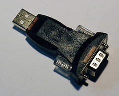
The looks of the USB adapter prior to the procedure are shown in this picture:
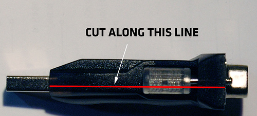
The first step is to cut open the overmolded plastic, so that we can work on the circuit unimpeded. The adapter used here is available in many local shops where I live, but any similar converter will do the job. With great care to not cut too deep (you risk damaging the components on the circuit board!), use a Dremel or sharp pen knife to make an incision along the red line:
Repeat on the other side of the adapter. On some of these devices, the plastic is not fully opaque, allowing you to see where the circuit board’s edge sits. Once you finish the cuts, carefully pry the two plastic halves apart, until you have something that looks like this (the SP213 is the large chip):
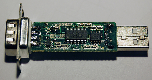
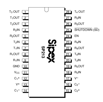
The TX and RX pins of the FTDI chip are connected to TxIN and RxOUT pins on the SP213 respectively. The TTL signal going into pin TxIN is then converted to a +10/-10 volt signal out of pin TxOUT. Similarly, the data signal coming from the serial port into pin RxIN at +10/-10 volts is converted to TTL (0/+5 volts) out of pin RxOUT. In this particular converter, the pins used are R4IN/R4OUT, and T1IN/T1OUT. As can be seen in the chip layout, the inputs to the FTDI are next to each other, so a simple solder ball will bridge them, and T1IN/T1OUT will have to be bridged using a wire.
Removing the SP213 can be done in various ways – if you have a hot air gun, you can clamp it with tweezers and hold the board up a few millimeters while you slowly heat it, until the board falls down from under the chip. You can also use a regular fine-tipped soldering iron and place a big solder blob along one of the rows of pins, then lift up gently, repeat on the other side. Clean excess solder with some copper wick.
The end result, after removing the chip and placing the bridges is as shown (forgive the ugly gray wire – it’s better to do it with insulated copper wire, but I didn’t have any left at the time).
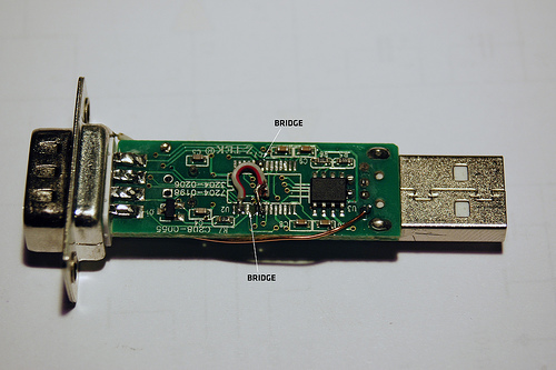 One final step required for some radios is to feed a steady 5 volts out of the DB9 connector. This can be solved by cutting the trace leading to pin 1 of the DB9 (which is not used for anything useful), and running a wire from the +5V pin of the USB connector (this is also shown on the above picture).
Finishing touches
If unlike me, you are good at handywork, you should be able to put the modified board back inside the plastic mold, and glue the cut shut. Otherwise, a heatshrink tube cover works just as well.
Part II – Radio-specific programming leads
Since I had an immediate problem to solve, the easy course of action was to build the cables required to program the GM300s and GP320s. With some luck, the GM300 cable should also program the GM350.
GM300 cable
Working off this schematic found on the very excellent BatLabs site (thanks for getting me out of many fixes, guys!), the following schematic was drawn:
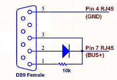
which resulted in this connector:
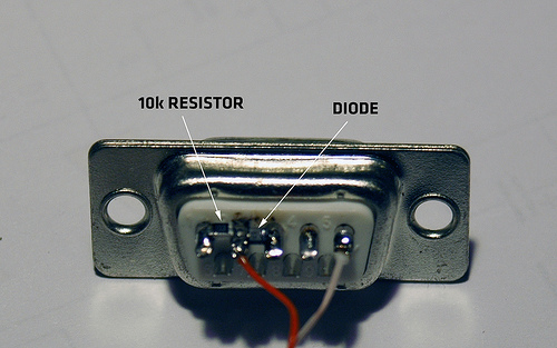 The diode and resistor used are 0603 SMD, as they fit very nicely between the pins of the DB9.
GP320 cable
This one was going to be more involved – contrary to the GM300, the GP3×0 series of radios doesn’t have an RJ45 connector, which is pretty standard and easy to crimp. Instead, it has a 13-way (what a lucky number to pick!) contact pad connector, which doubles for accessories and programming.
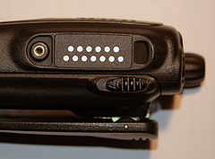
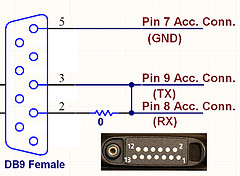
On a service manual, I found the pinout of this connector, and identified the ground, TX and RX pads – which as usual, appeared tied into a single bus for sending and receiving data. I assumed from some other schematics found on BatLabs that the same requirements would apply for this cable, i.e. a pullup to +5V on the data line, isolation via diode of TX and RX…but nothing worked. Eventually, I tried the simplest approach: bridge the TX and RX pins of the DB9 with a 0-ohm resistor. And it worked. This is the stupidly simple schematic of the GP320 cable:
I managed to concoct a three-prong stiff connector, which had to be held by hand against the three pads on the side of the radio, while driving the mouse with the other hand – not comfortable, and potentially dangerous (enough for testing it worked though!).
Part III – GP320 cable – reloaded!
Not happy with having to hold the DIY connector against the radio, an idea popped into my head – these radios come with a plastic cover that screws into place, guarding the connector against water and dirt:
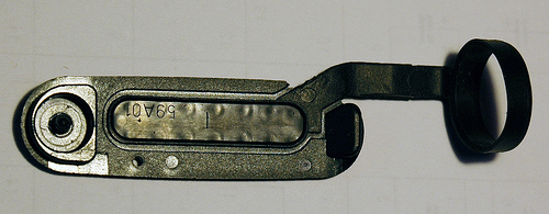 It appeared that the cover was made out of two pieces, a hard plastic lid with a molded-in rubber part, which covered part of the hard lid and formed the collar that clamps the whole thing to the antenna. If this rubber piece could be removed, and the plastic used to mount three spring-loaded contacts…we’d be in business!
Mill-max – the hacker’s friend
Mill-max is a manufacturer of all sorts of electrical contacts, one of their product lines being spring-loaded board-to-board pins. I had used the shortest pin on their catalog for another project, and had a few samples left. These pins can be ordered through DigiKey in small quantities, and they usually keep stock (part number 0900-0-00-00-00-00-11-0). The pins I had were very similar to the ones used in genuine speaker/mics and programming cables:

Inserting the pins
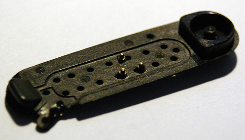
After removing the rubber part, the hard plastic cover looked like this:
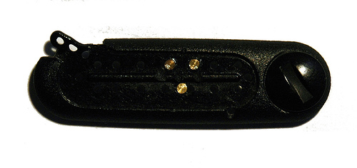
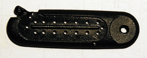 It was a matter of finding the location of the pads below, and drilling the pins in. Two factors caused this to turn out better than I thought – I didn’t have a 1.8mm drill (only 1.5mm), which is the pin’s barrel diameter, and even so, what would hold down the pins? The solution: drill 1.5mm pilot holes, and then drive the pins into them, melting the plastic by applying heat from soldering iron on the back of the pin. Done with care, the end result is this:
Cabling up
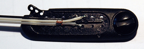
Once the pins had settled, and were checked for correct spring action (the molten plastic could have gotten into the barrel, locking the spring into place), a three-way flat cable was soldered to the back of the pins, and held down against the cover with a thin insulated copper wire:
 Gluing down
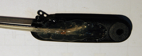
A quick shot of hot glue was applied to the top of the connector, which flowed a bit into the remaining open holes, fixing the whole assembly in place. This is what the connector looks like:
 And that’s all there is to it! I now have a very light, multi-use, USB programming interface for all kinds of radios – just by changing the connector layout on the female DB9, other radios such as Vertex and Icom could be programmed with ease.
Comments, suggestions and improvements welcome!