Today I was throwing old stuff away from my parents-in-law’s house, when I came across a Casio PB-1000 personal computer, which belonged to my wife. She told me ‘oh, that’s just a calculator I used at school, it used to be good for trig’. In fact, it is a very capable machine (in its time, now your TV’s remote has more processing power than this thing!), it has 8kB of RAM, an RS-232 and floppy drive port, graphic touch screen, and runs for 55 to 100 hours on 3 AA batteries. What really strikes me opening the device is that the keyboard is very similar to the ZX81’s, with all the most used BASIC commands overlaid on each key, and accessible using the shift key. Here is a picture of this ancient device, which brings back many fond memories, such as getting Pong to work.
Hardware
Die Bezeichnung Hardware beschreibt technische Ausrüstungen eines Systems wie zum Beispiel einem Computer. Einfache Systeme arbeiten direkt mit der integrierten Hardware während bei komplexeren Systemen meist eine Steuereinheit in Form eines Prozessor erforderlich ist. Die Hardware kann man besten nach der so genannten Von-Neumann-Architektur aufgeteilt werden.
Die Aufteilung besteht aus dem Steuerwerk, Rechenwerk ALU (Arimetisch-logische Einheit) und Peripherie-Gerät. In den heutigen Prozessoren sind zahlreiche Hardware-Funktionen vereint. Bei der Computer-Hardware erfolgt die Verwaltung sowie Steuerung über die Firmware. Ein Großteil der Hardware bietet eine FCC-Nummer über welche der Hersteller eindeutig identifiziert werden kann. Der User kann heute zwischen tausenden Hardware-Produkten wählen.
Vodafone HSDPA with the Huawei E220 USB modem
Went to my local Vodafone store to pick up the new Huawei E220 HSDPA USB modem, which with a 49 Euro monthly contract gives you 1GB of transfer at 1Mbps maximum, and free mobile to fixed landline calls – pretty good deal if you ask me. For 59 Euro you get 5GB of transfer, at the full 3.8Mbps that HSDPA offers. These are theoretical rates, as they will depend on a number of factors, such as how many people are also using the same cell, your coverage and the quality of the link.
We can argue all we want about how convenient WiFi is, being omnipresent et al, but in reality, it’s rather hard to get connected while on the road. Let’s examine the following scenarios, and you tell me the chances of getting connected over WiFi:
- Riding the train or bus home.
- Getting a lift from a friend in his/her car.
- Opening your laptop at a random location (cafeteria, bar, etc. that you haven’t before scouted for open WiFi).
- On a plane, waiting for the next free takeoff slot that you hope the pilot won’t miss because he was checking the fatness of his wallet.
Let’s be honest – free open WiFi is great once you have identified the locations where you can get connected, such as a friend’s house or the local coffee shop. Other solid commercial alternatives make it easier to find WiFi, as they tend to be present at well-known locations. Walk into any Starbucks or hotel, and you’re bound to find at least for-pay wireless.
For me, on the 30 minutes to 1 hour it takes to get home on the train or bus, being able to get connected is great. The convenience of simply opening the Mac and getting online beats the guesswork of WiFi. I tried getting the Mac working with my Nokia N93 over Bluetooth, but it was just too unstable – one day it worked, the next simply refused to even connect. A more in-depth review of the device is coming, once I get a chance to roam about with it for a while.
So far, installation on the Mac was pretty straightforward, download the setup package from Vodafone’s site (they don’t tell you this in the manual), which then enables the modem as a networking device. If you don’t follow this step, it can get recognized as a storage device, which is not particularly useful for a modem. The one thing I don’t understand is why it comes with a miniUSB cable that ends in two USB connectors, my guess is it’s power-related (some USB ports don’t provide the full 500mA they are supposed to provide).
Autopsy of a Fonera
Yesterday, I posted a few pictures of the opened Fonera, with a few initial views on the device. When I tried to plug it in, it failed to work, only the power LED lighting up. Neither the WiFi signal was coming up, nor the ethernet port was tickling the switch.
The only course of action? To open it up even more. So, the aluminium chassis came off, and that’s when I realized I had seen this before. The WiFi section, which includes the Atheros AR2315, crystal, filters, power amplifiers and ancilliary circuitry are housed inside this casing, and correspond to a reference design provided most likely by Atheros themselves. Check out the Meraki Mini router. For reference, I provide a side-by-side picture below (click for large image).

There is nothing wrong with using reference designs per se, as it is the fastest and easiest way to bring a product to market. If you don’t need to customize your design much, simply use what the manufacturer suggests, and you will be playing on the safe side. A perfect example is Bluetooth headsets, where CSR dominates the market. Virtually all headsets in the market use their reference design, with very little changes between them, other than physical placement of LEDs and buttons.
Block-by-block, here is an overview of the Fonera.
Power
Power is supplied to the Fonera via jack SK1, and is fed through a rapid fuse (Polychem type) to a simple drop-down regulator, which drops voltage from around 5V (4.85V as measured on the wall power supply, using a Fluke 179 multimeter) to 3.3V. The regulator appears to be an AME1117 (though the package markings read AME117), in its CCCT configuration, TO-252 form factor. The regulator is stabilized using three electrolyic capacitors. In these types of regulators, ESR (equivalent series resistance) of the input decoupling capacitors is very important, and this can usually be controlled nicely with tantalum capacitors. These are very expensive compared to electrolytic, however.
There is a second stage of regulation, this time done by an Anpec APL1117, which further drops the voltage to 2.5V. This supply appears to be used by the wireless subsection. Two ceramic capacitors stabilize the regulator.
Without the Atheros chip in place, the PCB drew 90mA at 5V, or 450mW. Since the device was not functioning, the total supply current with WiFi active could not be determined.
Memory
Two memory ICs are available on the Fonera, the first is an ST M25P64 serial flash, with a 50MHz SPI bus and 64Mbit capacity (8MB), in 300mil SO16 format. The fact that SPI has been chosen has the advantage that extra memory devices could be attached to the bus, but it has the caveat that it is slower than a parallel bus. Thus, flashing a new firmware could take a rather long time. Interestingly, there are two footprints on the PCB, presumably to fit a different size and format memory IC, one SO16 and one SO8.
The second memory IC is a Hynix HY57V281620E synchronous DRAM, with a capacity of 128Mbit organized in 16bit blocks. In practice, this results in 16MB of RAM available to the processor.
Ethernet
At the heart of the wired ethernet subsystem is an Altima AC101 ethernet transceiver, capable of 10/100 full duplex operation. The IC is placed on the bottom layer of the PCB, and runs off a 25MHz crystal, strangely placed next to the main power regulator, where it could absorb electrical noise. Usually, crystals are placed well away from sources of interference. Nothing else too exciting here, the transceiver is connected to a standard RJ45 socket, TP1.
Wireless
The wireless section is the most interesting. This is where the Atheros AR2315 single-chip WiFi processor lives. Little public information is available about this or any other Atheros chipset, so it is hard to figure out exactly how it is put in place, but a few details are clear.
First, the chip gets hot. This is why a double heat-conductive adhesive tape bonds the surface to the metal cover, and in turn to the heatsink placed on top. The processor runs from a 40MHz clock source. After the Atheros core, come a couple of filters, and a power amplifier stage. This then runs off to the two antenna tracks. The first antenna exits the aluminium cage and runs up to a test connector. This connector breaks the antenna track when the right mating plug is inserted, which is then fed into a dedicated RF analyzer, which validates that the device is within constraints.
After the antenna test point, there is a split, which can be configured using a zero-ohm resistor, to run to an internal solder pad, or to a PCB-mounted right-angle SMA connector. It is unclear why they chose to use the solder pad, as an in-place soldered connector needs less handling than soldering a pigtail by hand. Besides, my intuition tells me the losses would be lower – I will test this when I get a working Fonera. Both tracks run through an impedance matching network, consisting of two capacitors to ground from the RF track, and an inductor between the capacitors . The purpose if this small circuit is to get the impedance of the PCB track as close to 50 ohms as possible. If the track impedance is mismatched to the antenna, losses take place.
The second antenna runs straight to a PCB pad, where a pigtail may be soldered, also passing a matching network. Below is a picture showing the details of this subsection.

Interfaces
There are two IDC-style connectors on the PCB, one 2×5, and one 2×7 but unpopulated. The 2×5 looks like a serial connector, as only power, ground and two tracks lead out from it. The layout has to be studied in more detail to confirm this assumption.
It can be speculated that this is in fact a serial port, but without the AR2315 pinout, this cannot be determined for sure. The 2×7 header seems to be a JTAG interface, possibly compliant with MIPS EJTAG 2.6. The mapping of the header pins to the AR2315 BGA balls is shown below (thanks for adding a row/column silkscreen for the Atheros chip, and thanks to the OpenWRT project wiki for the JTAG information!):

Between the Ethernet jack and the empty SMA footprint, there is a footprint of 6-way header, which needs a bit more study to determine where it leads internally [I will update the post when I find out –Mike].
Conclusion
This is a very compact and simple WiFi router, designed not for being easy to hack, but for lowest cost. The cheap power regulator, use of large SMDs and choice of pigtail rather than board-mounted SMA connector point in this direction. There is only one port which could be used for something useful, if it is indeed a serial port, the only two GPIOs available being the WLAN and Ethernet LEDs – as long as the Ethernet LED is not controlled by the Altima but by the Atheros. The power LED is on as long as there is power applied to the device, so there is no control over this by the Atheros processor. Power consumption is a bit high, considering the wireless device was not present. The PCB layout is very professional, except in a few particular cases such as the large crystal, but overall, quite nice.
In all, a very small device which could have a lot of potential, had it not been for its lack of I/O. It is unclear whether the router will accept custom firmware, as there are rumors that an encryption & signature system is used. The Fonera is probably OK for regular use by Foneros, but it does not have the hackable edge of the Linksys WRT54Gx. The only suprise could come from the edge connector, as of yet of unknown usefulness.
References
Atheros AR2315 chipset website section and product brief.
The naked Fonera
After a few days of silence, digesting the hubbub created by my analysis of Fon’s status, I’ve put my head back into more useful things than answering hate mail and out-of-line comments (thanks to those who provided balanced views, either for or against!). So, I decided to open a Fonera and see what lives inside.
A full review is coming, but first impressions:
- The plastic casing looks and feels very nice, the molds must have been expensive, as the different parts mate very well.
- Inside lives a single PCB, with components on both sides. The top holds the bulkier components, such as power regulator, RAM and WiFi section, inside an aluminium RF shield.
- The PCB looks professional and well laid out on first inspection.
- Components used (I haven’t opened the aluminium chassis yet) are older SOIC and TSSOP, thus cheaper to handle and solder. Balled components require from special handling, such as baking in hydrogen for 24 hours to dry them before soldering, etc.
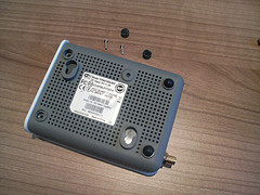
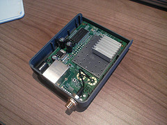
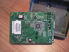
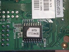
Here are some pics (click each photo for bigger views on Flickr) I have taken with a Nokia N93 (really nice phone btw, mini-review coming):

The underside of the case, with screws off.

Perspective view of the top PCB.

Bottom side of the PCB.

Sticker on the flash IC showing the firmware version.
Digi – an example of excellent costumer support
What do you do when you need to embed WiFi into a project really quick? You look for OEM modules – one of the best manufacturers being Digi. They make, amongst other variations, the Wi-ME, a small box that has a RTOS chip (it can be made to run Linux apparently) and the WiFi adapter, with a serial interface and GPIOs that go to your application. In essence, you can bridge a serial port to a TCP or UDP port and stream data to the internet, all without messy wires!
![]()
After looking at the ordering page, I duly contacted the spanish distributor Matrix. I needed two modules by this last Monday, and so I requested to have the devices shipped by Friday last week. It all turned out into one big mess, with vague excuses about not being able to ship due to warehouse problems, or that the proforma could not be generated – and so I could not pay, and they could not ship…to cut a long story short, I got the units on Tuesday.
It usually is not a problem to have a shipping delay, but in this case, I arranged a meeting with the mechanical engineers working on the project, in order for them to see the device and fit it into the 3D plastics project. They actually measure the parts, as they say working from datasheets can usually spell trouble, so ideally they would take them away after the meeting. Had Matrix simply said “we cannot send it until Monday”, I would have arranged the meeting on Wednesday – no worries. But, as it frequently happens, they wanted to look good, without having the solid ground under their feet to do so.
When a company makes a commitment, whatever it may be, it has to stick to it. And when the costumer calls, obviously pissed off at the poor performance and the mount of problems he has landed on, you have to be hellbent on fixing the situation. If the person answering the phone cannot handle the situation, he/she must be trained to transfer the call to someone who can.
What did I do? I emailed the CEO, Joseph Dunsmore. His email address is not published on Digi’s site, but if you look on the Management Team page, and scroll down a bit, Jan McBride’s email is displayed. It was a case of formatting Joseph’s name in the same manner as Jan’s email, send the diatribe, and wait. The next day, I got a reply from Joseph, telling me he would follow up the case with Digi’s Managing Director in Europe. Not three hours had passed, and I got a call from Digi’s top man in Spain, who was very supportive and understanding. By this time, I had been so smoothed over, that I really didn’t want to complain anymore! The conversation ended up very well, with Digi offering their full support on our development, and a visit arranged sometime next week.
Would I recommend Digi to anyone deciding about whether to use their products? Absolutely!
The Chumby – alarm clock? GPS navigator? no – WiFi device for $150!
Yesterday I read some news about Chumby, a new WiFi device being released soon, costing $150, and which looks like an alarm clock on steroids. It features a color screen, the ability to run widgets, hackable hardware, and a squishterface (just made that up, to try to describe the squeeze sensor that the soft case uses to provide user input).
The company behind the Chumby actively promotes hacking the product in any way you want, so this could become another Roomba, albeit cooler (yes, I know, the Roomba moves, so what!). I have signed up to try and get an early sample, let’s see if they consider my arguments.
A few words of constructive criticism – when creating an account, the country drop-down list is not in alphabetical order, so you spend quite a bit of time trying to find yours (US users will have it easy, as it is the default). Additionally, once the steps are completed, you are asked to enter the device ID and give it a name, after which you end up staring at a white page with the big black words: “Application error (Rails”. Whatever that means.